The need for a hands-on project
Almost all of my personal projects rely entirely on software solutions, in which I either set up existing tools or write them myself. Even though the projects and software in question vary greatly, interacting only with code can get stale after a while. This encouraged me to start a hands-on DIY project. It specifically appealed to me since I’ve rarely built anything physical during my education, so it was mostly uncharted territory. I looked for something in my daily life that would benefit from a simple device I could build myself.
One thing came to mind: my house has poor insulation, so some rooms have higher humidity which attracts mold. While there are existing solutions for monitoring humidity, I wanted something simple and portable that I could build myself without spending much money.
This is why I decided to build a portable monitor to measure temperature and humidity. These were the features I wanted:
- Ability to measure air temperature and humidity
- A small screen to display the data
- Battery-powered operation for portability around the house
- Battery percentage display to know when to recharge
- A small, portable 3D-printed case to house everything
Designing the circuit
The problem was that I didn’t know where to start, as I had no experience with electronics. This hurdle was quickly cleared with the help of Claude, which suggested the core components and a basic circuit design. I used this as a starting point for my research.
After researching for a few days, I settled on the following components:
- SH1106 - 1.3" OLED display
- DHT22 - temperature and humidity sensor
- ESP32 - microcontroller for fetching data and driving the screen
- 2000 mAh 3.7V Li-Po battery - powers the device
- TP4056 - battery charger module
- Rocker switch - power switch
- 2x 47k$\Omega$ resistors - voltage divider for battery monitoring
All of these components are easily found on websites like AliExpress for around 20€ total.
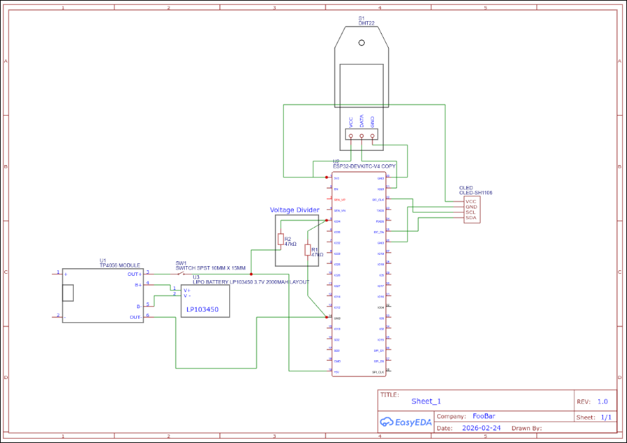
The reason I needed a voltage divider is that the ESP32’s ADC can only measure up to 3.3V, while the battery can output up to 4.2V when fully charged. The voltage divider reduces the battery voltage to a safe level. Since two resistors of the same value are used, the voltage is halved, meaning the maximum voltage the ESP32 sees is 2.1V—well within its safe range.
Before building the circuit, I designed it using EasyEDA. This helped me visualize the connections and how the components would fit together.
Prototyping
For prototyping, I used a full-width breadboard and 10 cm jumper wires.
I programmed the ESP32 using the Arduino IDE, which I was already familiar with. Most of the code was adapted from the “Examples” section after installing the ESP32 board manager. For the display and sensor, I followed these tutorials:
- Display - Demo 6: How to use Arduino ESP32 to display information on OLED
- Sensor - ESP32 with DHT11/DHT22 Temperature and Humidity Sensor using Arduino IDE | Random Nerd Tutorials
Since I chose an OLED screen, I was concerned about burn-in—permanent damage caused by displaying static elements like “Humidity:” for too long. To prevent this, I implemented a simple screensaver that turns the display off for 10 seconds for every 5 seconds it’s on. During those 10 seconds of inactivity, I also put the ESP32 into deep sleep to save battery. To further increase the display’s lifespan, I added a random pixel offset for the text so that static labels don’t always use the same pixels.
You can find the code in this repository.
MVP (Minimum Viable Product)
The current prototype is shown below.
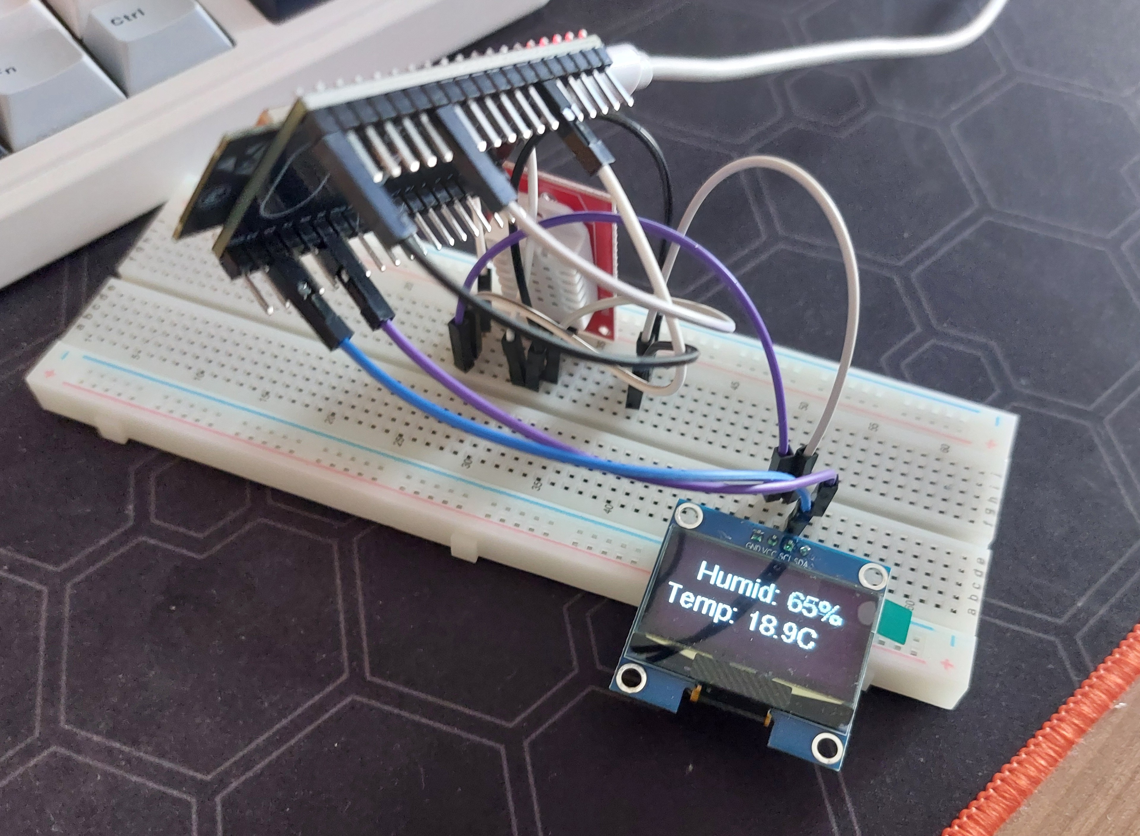 It’s not the prettiest setup, but it’s a working proof of concept. The ESP32 is elevated because it’s so wide that it would otherwise cover most of the breadboard holes, leaving no room for jumper wires.
I’m still waiting for battery and resistors to arrive so I’ll update the article once I integrate them into my prototype.